Tesla coil
I have planned to build my own coil for a long time, but this summer I was fortunate to have all necessary parts needed for building one. It's a dream come true!
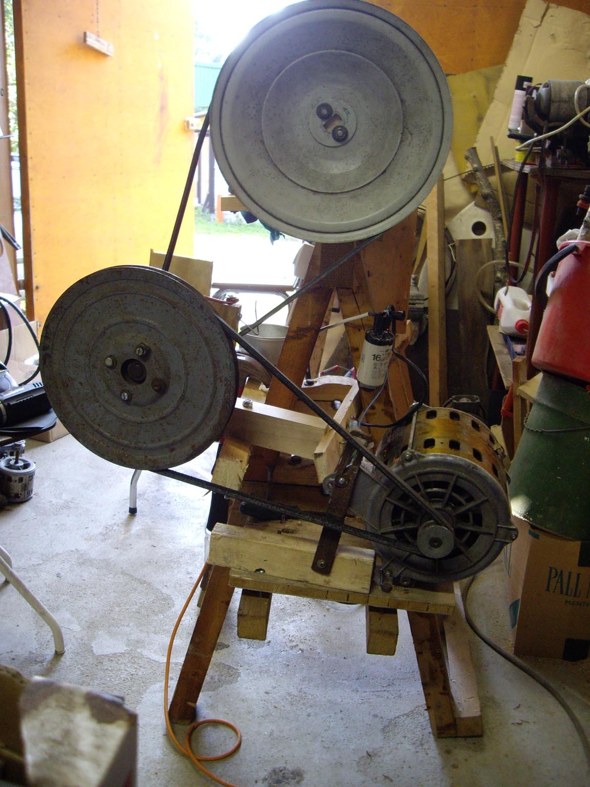
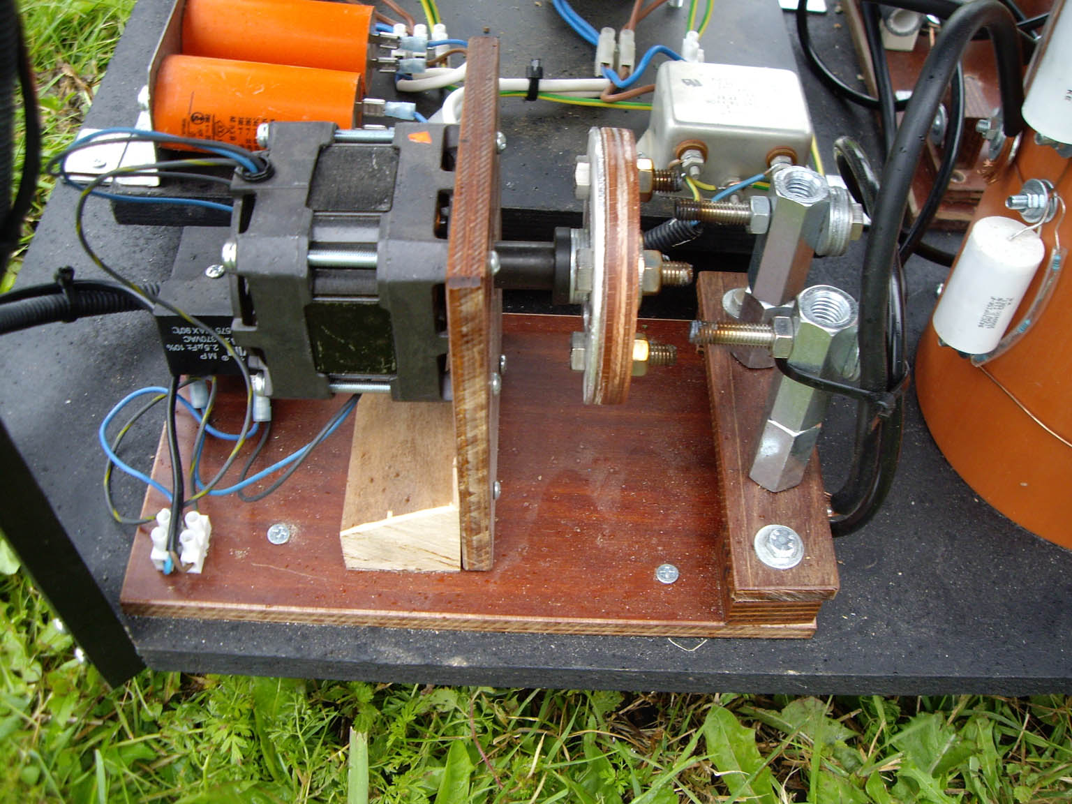
First of all I needed a winding apparatus to wind my secondary coil on. My father had an old wooden lathe (homemade ecostyle =)) that he didn't need. It had no motor just the frame and bearings (from a motorblock and a bicycle). I found one old washing mashine motor that I did use and some wheels, also from washing mashines.
WM-motors is constructed to be run with two speeds. One for normal washing and the other for centrifuge. I had to get the speed down to about 20 rpm. So I used three wheels (diffrent size in diam.) and straps to get the speed down to about 14 rpm (bearing for the middle wheels is from a water pump). I also installed a pedal from an old singer sowing mashine to be able to gain control over speed and start/stop. It took me about three weeks to finish this lathe. Coilwinding became much easier with this apparatus :-)
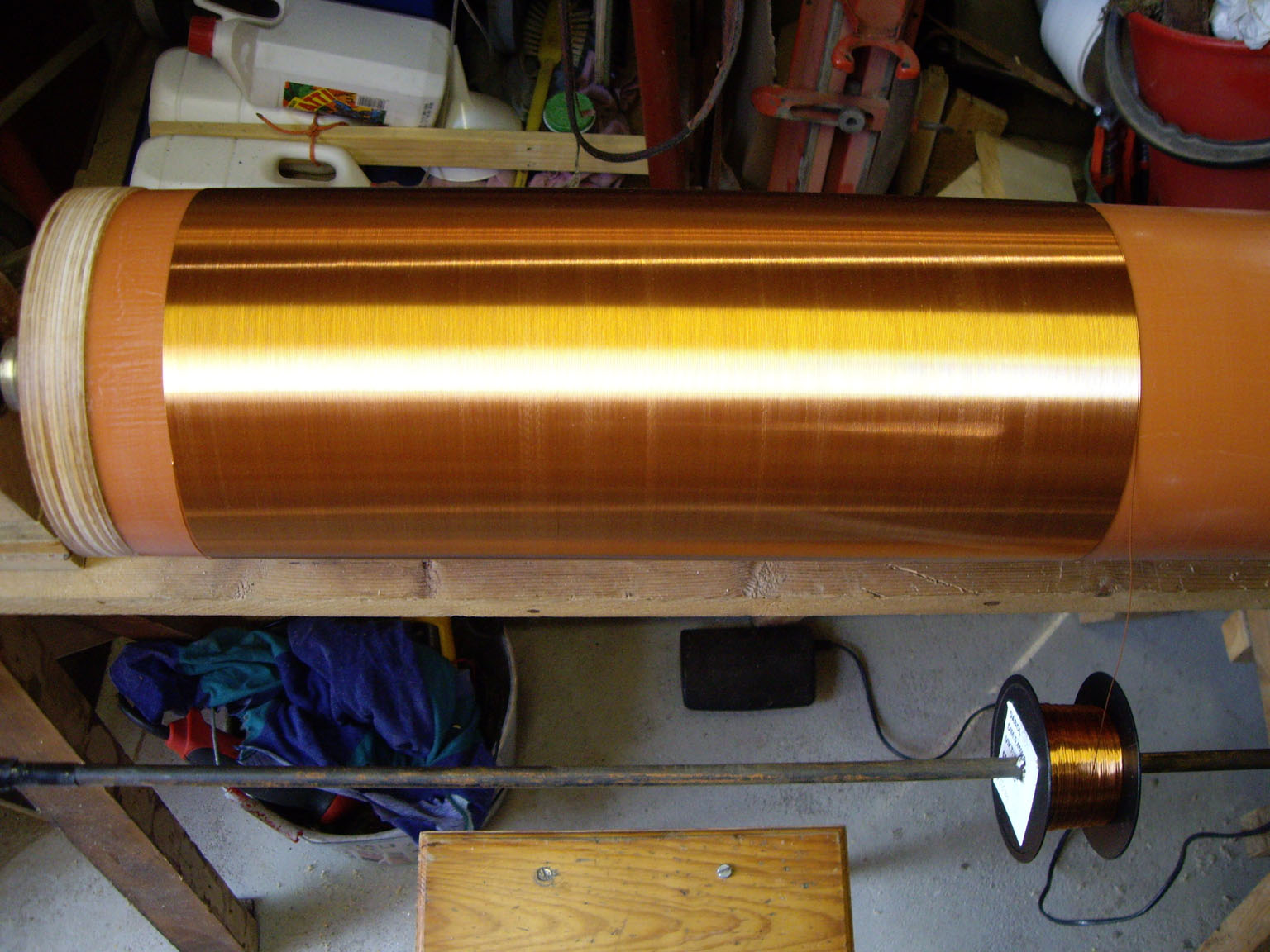
Secondary coil consists of 800mm PVC duct 160mm in diameter. Winding the secondary took about three hours. Six thin coats of polyurethane varnish was applied while coil still rotating to get an even layer. I used 1kg of 0,45mm (25AWG) varnished copper wire. This resulted in 699,4m copper wire and 1392 turns. The ends were plugged with 5mm polyacrylate plates glued in place with superepoxy. I used two M8 bolts for mounting coil and toroid. Calculated inductance is 62,69 mH and selfcapacitance 11,83 pF which translates to about 184,8kHz. Additional top load does however lower resonant frequency to about 121,5kHz.
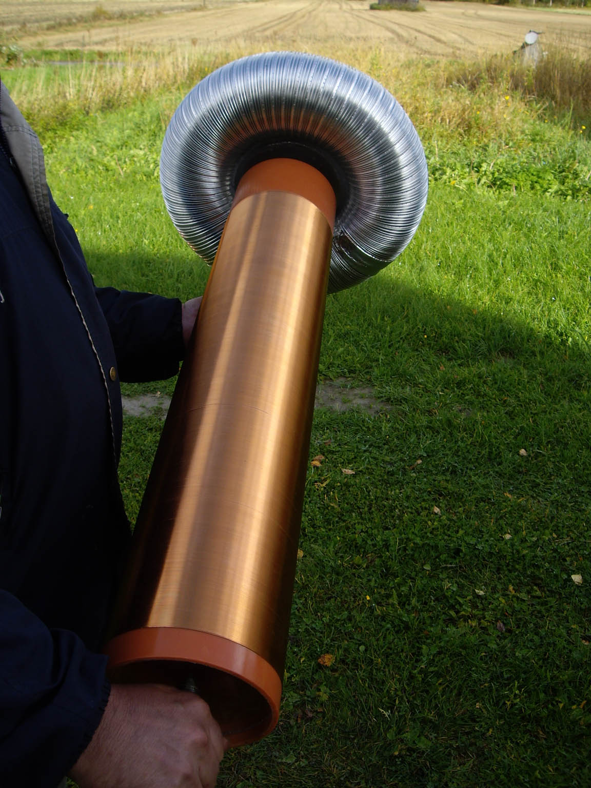
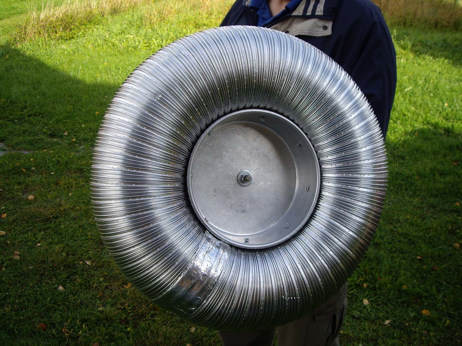
The toroid for this coil was made from one aluminium cake form (95mm in diam.) and kitchen aluminium duct tube (110mm in diam.).
Toroid capacitance was calculated using Mark Rzeszotarskis equation (all calculations made with wintesla 5.0)
Further improvements is to make a larger toroid which comes on top. This is to get larger capacitance and lower the resonance frequency of the coil and get better sparks.
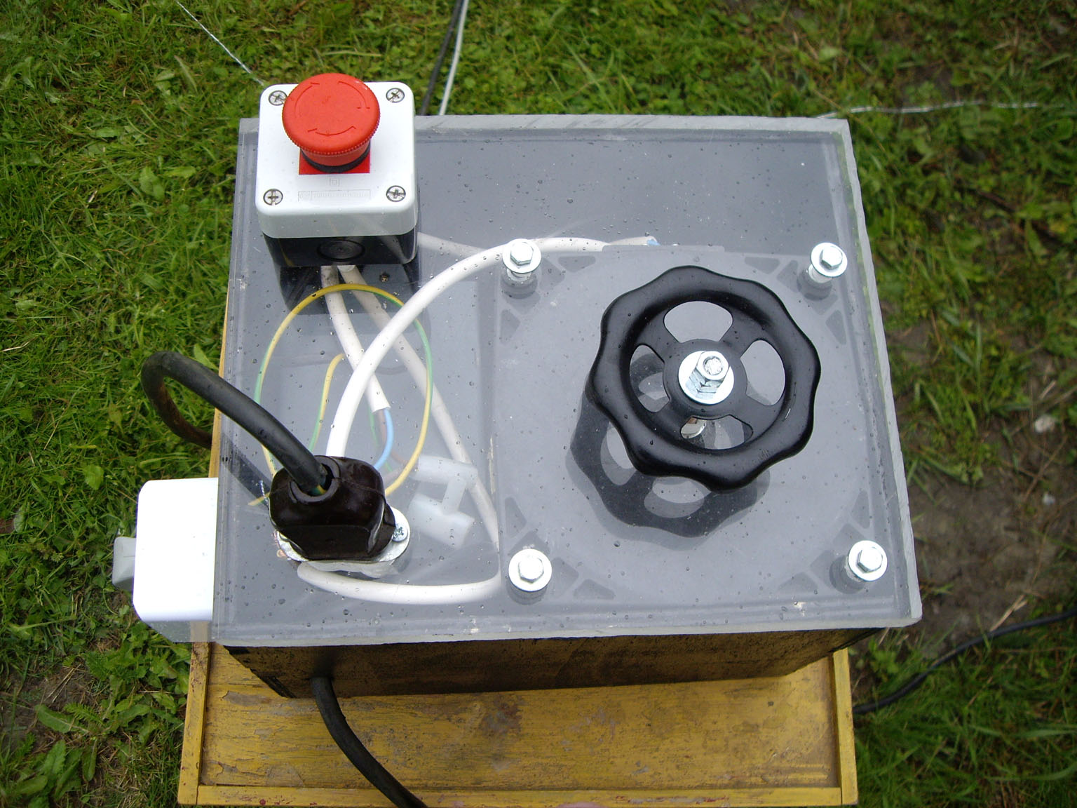
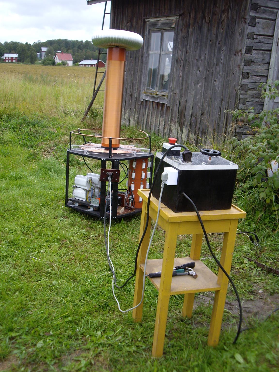
Finished secondary coil with toroid mounted. Left picture shows entire setup with control box.
Some parts needed for this project was ordered through ebay seller rainylk (http://stores.ebay.com/TeslaStuff)