Etusivulle | Back to main text
The invention concerns an arrangement for the recording of sound waves, where the sound waves influence the luminosity of a light source, whose light beams are projected on to a film band. The invention suggests as light source a gas flame, which is fed through a tube with a throttle valve.
In the drawing (Illustration A and Illustration B) the invention is presented in several examples of application. In
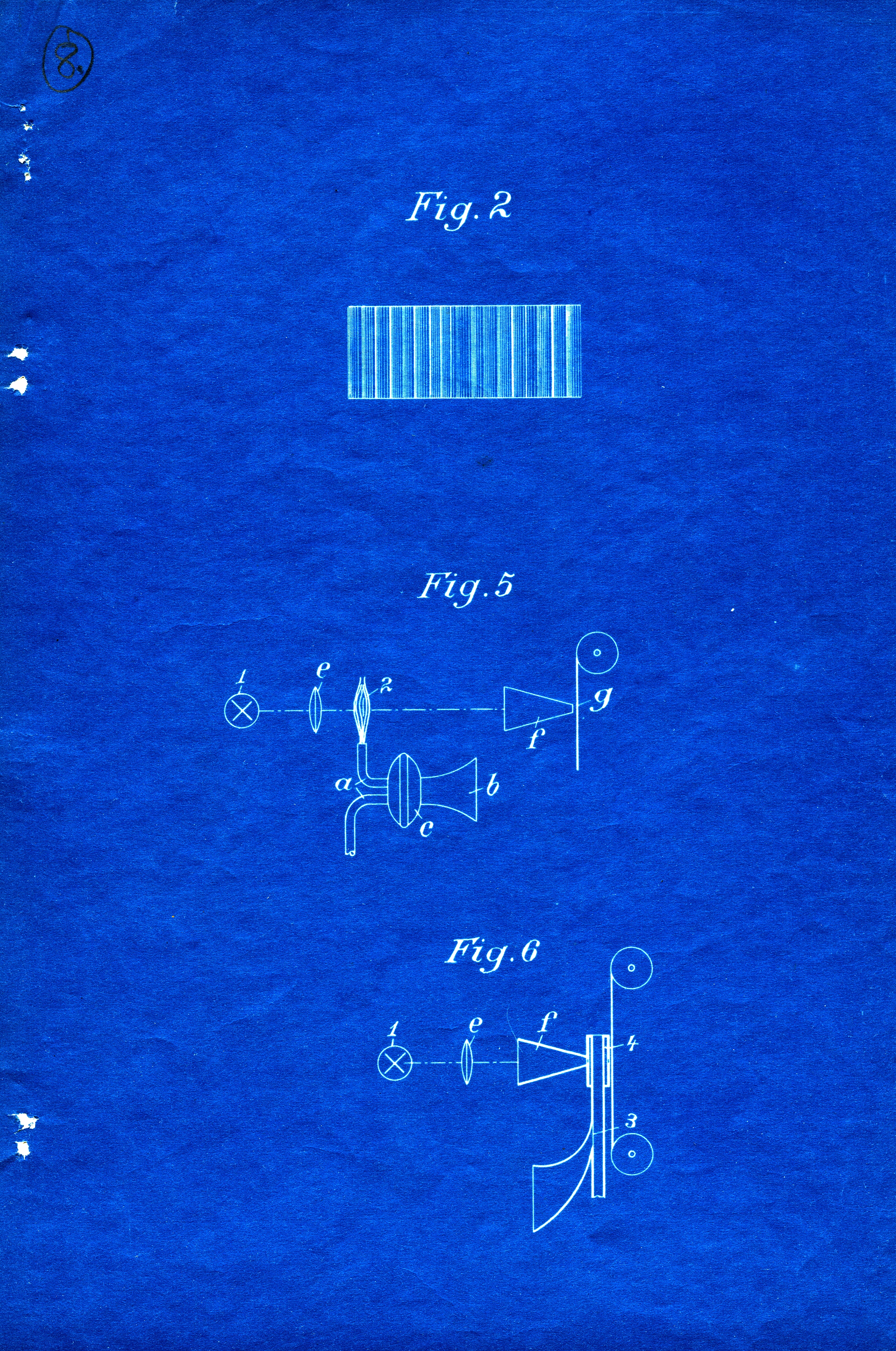
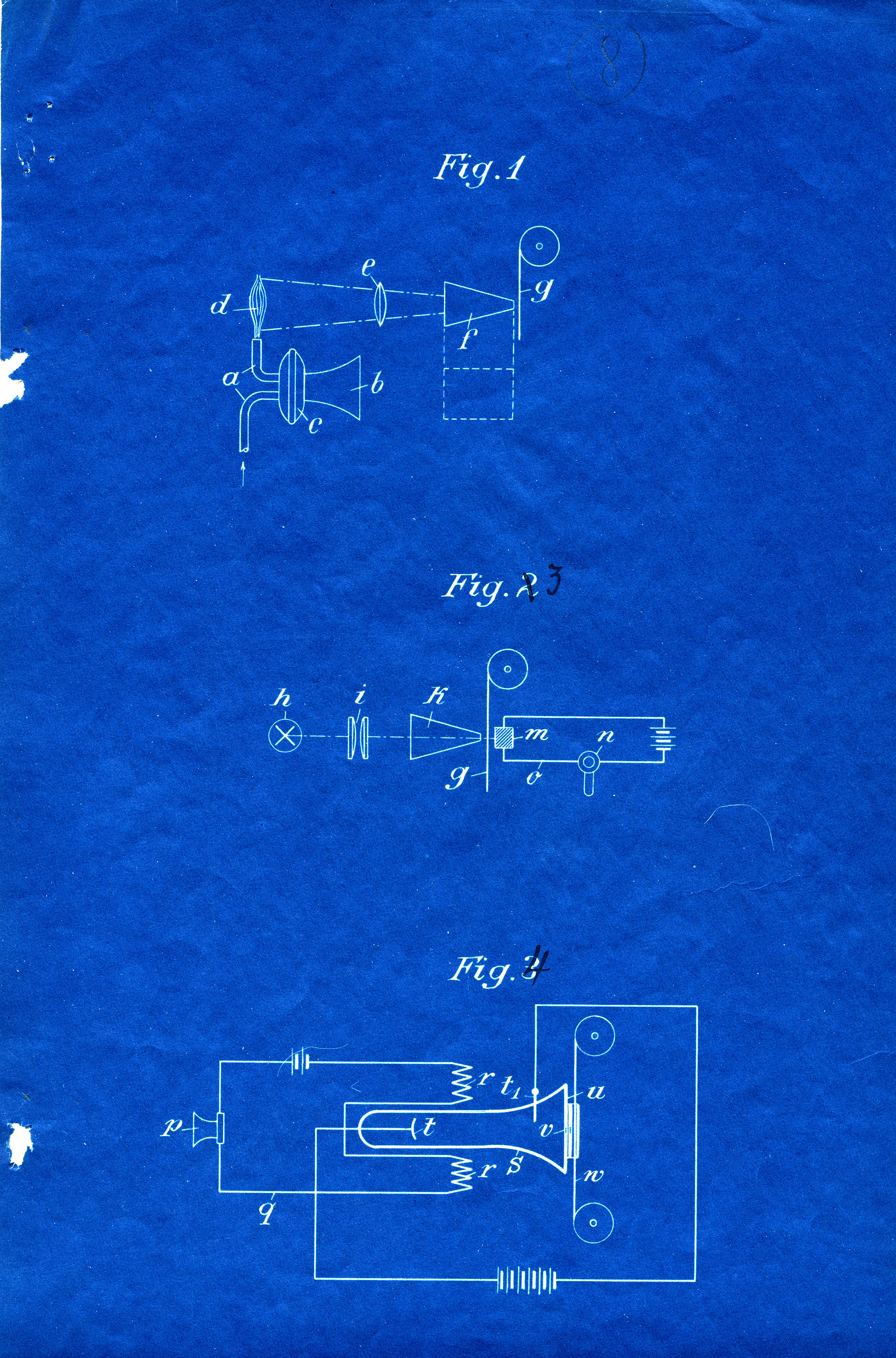
In the gas tube a capsule c is inserted, which is equipped with a funnelling device; in it a membrane that influences the cross-section of the tube a is arranged. When someone speaks into mouthpiece b, the cross-section of the tube changes and thus also the luminosity of the flame d [Fig. 1; editors note]. The beams emanating from here are transmitted through a lens e and a hopper onto film so that this depending on the changing luminosity of the gas flame acquires more or less transparent places (Fig. 2).
In the model of Fig. 3 [Fig. 5; editors note] any constant light source 1 is used. To influence the intensity of the light beams falling on to the film band, between the collecting lens e and hopper f a coloured gas flame has been arranged. The gas tube stands, as in the first model, under the influence of a membrane, to which sound is transmitted via funnel b. Depending on the sound reaching the membrane, the gas supply is more or less throttled and the flame for the light beams emanating from light source 1 is more or less transparent, so that on the film band more or less illuminated stripes appear.
Instead of the coloured flame, coloured gas (smoke) may also be used. Such an application is presented in Fig. 4 [Fig. 6; editors note]. The gas supply is throttled more or less by the sound waves through a very susceptible membrane 3 so that the gas streaming through the transparent duct arranged between the hopper f and the film band is more or less dense and therefore has different transparency for the light beams.
Several light sources may be used, and several gas flames can be applied to the same film band. The membrane 3 from Fig. 4 may also be permeable so that the sound waves can reach the gas flow and dilute it accordingly.
In Fig. 5 [Fig. 3; editors note] the sound is recorded through a microphone p, in whose circuit q there are two opposed selenium cells r, r; between them is a cathode tube s, whose electrodes t, t1 are supplied with electricity by a high-voltage generator. At the front end of the tube s is a shutter u impermeable for cathode rays, which has a small window v. Behind this the film w is moved along. The speech currents in circuit q create various fluctuations of the selenium cells r, r which move the focus of the cathode rays in the window more or less along a horizontal axis and thus illuminate the film behind it to a greater or lesser extent. [Last sentence crossed out from the manuscript; editors note].
Claims: [3]
The invention concerns a device for the recording of sounds on film bands and such. According to the invention, this is achieved as follows: the light beam projected onto the image band is influenced by the sound waves to be recorded to such an extent that these change the luminosity of the light beam and thus create more or less lit spots on the light-sensitive image band. The image band thus produced is then inserted in the usual way between a selenium cell arranged between a light source and a telephone circuit. Due to the various translucence of parts on the image band, the resistance in the selenium cell and the telephone circuit changes accordingly, so that the telephone renders the sounds on the image band.
In the drawing (Illustration A and Illustration B) several examples for application are represented:
A capsule c with a trumpet b has been inserted in gas tube a, inside which a membrane that influences the cross-section of tube a has been arranged. Thus, when someone speaks into the mouthpiece b, the cross-section of the tube will change and thus the luminosity of the flame d [Arrangement shown in Fig. 1; editors note]. The beams emanating from the flame are funnelled and transferred through lens e onto film, so that the latter, depending on the varying luminosity of the gas flame, acquires more or less transparencies (Fig. 2).
The equipment serving for reproduction (Fig. 3 [corrected in ink from Fig. 2]) consist of a light source h, a condenser i, a hopper k and a selenium cell m, which is arranged behind it and which sits inside the electric circuit c of a telephone n. The film g is passed along between the hopper k and the selenium cell, so that they, depending on the more or less transparent spots on the film band, are more or less lit and their resistance changed, so that the telephone u is set in operation.
Instead of a gas flame, electric light could also be used.
Fig. 4 [corrected in ink from Fig. 3] shows such a set-up. The sound is recorded through a microphone p, in whose electric circuit q two opposite solenoids r, r are placed; between them is a cathode tube e whose electrodes t, t1 are supplied with electricity from a highvoltage generator. At the top end of the tube 1 a shutter u has been installed that is impenetrable for cathode rays and has a small window v. Behind it, the film w is moved along. The vocal currents in the electric circuit q cause different vibrations of the solenoids r, r, which deflect the cathode rays more or less from the window v and illuminate the film behind it more or less. An electric lamp could also be used, if the luminosity is variable through changing the electric resistance. (The change of resistance could, for example, be induced by including a selenium cell into the circuit, which is directly lit more or less through a mirror connected to the membrane of the mouthpiece.)
In the application according to Fig. 5 any constant light source 4 can be used. To influence the luminosity of the light beam falling on to the film, a coloured gas flame 2 has been arranged between the lens e and the hopper f. The gas pipeline is, as in the first example, influenced by a membrane which receives sound through a funnel b. Depending on the sound that reaches the membrane, the flow of the gas will be more or less throttled and the flame for the light beams from light source 1 is more or less permeable, so that more or less illuminated horizontal stripes appear on the film band.
Instead of the coloured flame a coloured gas (smoke) may also be used. Such an application is presented in Fig. 6. The gas flow is throttled more or less through the sound waves by a very susceptible membrane 3 so that gas streaming between the hopper f and the filmstrip fed through an invisible gate 4 is more or less dense and therefore has different permeability for various light beams.
There could be different light sources and several gas flames for impact on to one and the same film band.
The films produced in the following method have the advantage of achieving an even luminosity across the space of the selenium cell.
Patent claims:
[1] This application filed under T19080 has two German versions: a new description marked in pencil (that is, retrospectively) IV/1913; and a longer version, an Attachment, with six claims, dated retrospectively V/1913. The version dated IV/1913 is the actual application text; the Attachment is either an earlier or later draft. Editors note.
[2] Tigerstedt apparently renumbered the figures at some stage, and made a mistake in numbering here: these actually should be numbers 3, 4 and 5 for this to be in line with the text that follows. Editors note.
[3] The Claims for the new version are attached to the file in English, but this translation has apparently been added later since the address is given as Platanvej in Copenhagen, where Tigerstedt moved in 1918. Editors note.
[4] The figures in the applications drawing supplement have been renumbered. It would appear that the longer, draft version presents four different mechanisms for recording sound in Fig. 1, Fig. 3 (corrected as 4), Fig. 5 and Fig. 6, and one for the reproduction of recorded sound (Fig. 2, corrected as 3). The new description omits the reproduction mechanism and describes only the recording mechanisms Fig. 1, Fig. 3 (corrected as 4), Fig. 5 and Fig. 6 but refers to a different numbering, which is also contradicted within the text itself.